Dec 15, 2021.
Deep apologies to all. My original analysis of Nov 11 had many inaccuracies.
Thanks to Jeff Roberson who pointed out a reversed force vector in the Drive Train figure. I have hopefully corrected most of the errors in this version (V19). The propeller now rotates in the same direction as in the videos of Blackbird. I have also clarified the vector math conventions making them easier to follow.
SeaBee
October 2023
I’m honored to have Rick Cavallaro, Blackbird’s creator and pilot, comment on this blog.
Rick rightly points out that my simple attempted demonstration (Fig. 6) of Bernoulli’s principle, with a spoon in running water, is actually more the Coanda effect where a passing fluid is attracted to a surface and follows its contour. I have added a correction and new photo.
Can a wind-driven vehicle go straight down wind faster than the wind speed? (FTTWDDW) Derek Muller’s YouTube channel “Veritasium”, and the image above show Rick Cavallaro’s brilliantly designed “Blackbird” propeller-driven cart. They say it has been done. See their video https://www.youtube.com/watch?v=jyQwgBAaBag
Wikipedia has the best explanation I’ve found at: en.wikipedia.org/wiki/Blackbird_(wind-powered_vehicle)
Kirk McDonald of Princeton University gives a great summary of the history of similar efforts with 98 references (PDF link): http://kirkmcd.princeton.edu/examples/yacht.pdf
Intuition suggested otherwise: to ‘sail’ downwind faster than the wind one would need a machine which could first accelerate from stationary up to wind speed – no problem – but then to go faster than the wind, one would have to keep accelerating from that point in time and space where the apparent wind on your craft had dropped to zero. Sounds impossible!
UCLA Astronomy and Physics prof. Alex Kusenko, while claiming he has significant sailing experience, lost a bet of $10,000 as witnessed by Bill Nye and Neil deGrasse Tyson. Alex claimed it could not be done saying that wind gusts and a higher wind speed at the prop height, rather than as measured at the cart, explained an observed momentarily high cart velocity. I’m sorry I cannot find any comment on the outcome of the wager from Nye or Tyson.
After much thought I suggest the following analyses might illustrate what is actually happening in a clear manner without resorting to plots of trig functions, etc.
General Physics Principles:

Figure 2
1. A balloon in a steady wind surely only travels at exactly wind speed and exactly in the wind’s direction.
That great old movie “Around the World in 80 Days” showed a global circumnavigation of approximately 24,000 miles in 80 days (averaging about 12.5 avg. mph). But did Niven and Cantinflas actually beat the laws of physics by doing it in (spoiler alert) 79 days, or just over 1% faster than the wind, when crossing the date line was included in their calculations?
 Figure 3
2. A balloon drifting low over a flat desert, in a 10 mph West wind, could lower a wheel-driven electrical generator (G) which could power a tow cart (M) motor-driven by an electric motor. But due to the second law of thermodynamics (Entropy always increases), and ever-present frictions in the generator and motor, the magnitude of the backwards (Westward direction) drag load of the generator will always be a little greater than the pulling power of the motor towards the East. As the interesting point of 10 mph balloon speed is approached the tension on the generator tow rope is eased by reducing the power generated in a vain attempt to reach 10 mph. This results in our complex balloon actually travelling a little slower than the 10 mph speed of the West wind, showing us that you cannot go downwind faster than the wind, at least when using a balloon, with or without, electrical propulsion devices. Or could you? Think very carefully before you answer! Remember there is a lot of kinetic energy available as the balloon passes over the ground at 10 mph, and not much of that energy would be needed to make it accelerate only 1 mph more to go faster than the wind!
3. Energy is needed to propel a wind driven craft. Such propulsive force can come from tapping into the kinetic energy available when there is a difference in velocity between the air and the ground (or water). That velocity difference can come from moving air (wind) over stationary land or water, or from stationary air over a moving body of water (river or ocean stream). A dramatic example of this latter case by Artemis Racing is shown in: https://www.youtube.com/watch?v=q2il8Fagbyk
where the Amazon River, flowing at 10 mph on a still air day, creates an apparent 10 mph wind sufficient to drive a foiling catamaran back up river (against the current) at 30 mph!
The problem is: how can one find the potential or kinetic energy difference needed for further acceleration when a land craft is travelling straight downwind at 10 mph in a 10 mph wind?
Sailing Theory
At age 16 Alen MacWeeney and I canoed the River Shannon and tributaries for a month in a homemade craft, using a bed sheet for a sail when there was wind. We sadly discovered, as did the square rig sailors of old, that we could not sail upwind at all. We could sail: 90 degrees across the wind “Beam Reaching”; at 45 degrees angle off the wind direction “Broad Reaching”; and straight downwind “Running”. To make any progress in an upwind direction in a canoe or sailboat would have required a keel, or centerboard, or a good skeg, and an airfoil section sail. The Egyptians seemed to have discovered this thousands of years ago with their elegant lateen-rigged feluccas on the River Nile, but they kept the details secret for a long time.
Part of answer to the Blackbird question lies in the application of Bernoulli’s principle to and airfoil section, sail-like, propeller.
From energy conservation laws: the faster air or liquid moves, then the lower its pressure becomes. For sailing, and flying, you see this principle demonstrated in the use of a curved, airfoil shape, cross-section of a wing, sail, or propeller.

Figure 4
Fluids (air, water, etc.) flow faster over the curved top of the airfoil shape than across the bottom when the flow is laminar, or non-turbulent. Some think that is so the upper fluid can “catch up” with the slower medium underneath which only had to move a shorter distance across the bottom of the foil. The faster speed of the fluid on top, perhaps surprisingly, results in it having a lower pressure according to Bernoulli. See: https://en.wikipedia.org.wiki/Bernoulli%27s_principle and others.
Including an ‘angle of attack’ of 10 to 20 degrees between the airfoil section and the wind adds to the lift effect by increasing the pressure below the foil relative to the low pressure on top. In optimum conditions this results in a force (red) which can be ‘resolved’ into two separate forces of ‘lift’ (green) and ‘drag’ (blue).

Figure 5
A flat surface could be used instead of an airfoil section but it is not nearly as effective – Look at the flat fan blades on cheap cooling fans: they create noise from turbulence and don’t move the air as efficiently.
[Revision Needed] “A beautifully simple demonstration of the Bernoulli reduced pressure lift process is made by delicately suspending a spoon near a stream of laminar flowing (non-aerated) water from a faucet. Move the spoon towards the stream so that the back of the spoon just contacts the water. If the water is turbulent it will splash off the spoon and push the spoon away, but when the water flow is smooth and laminar the opposite happens: Bernoulli’s low pressure draws the spoon into the stream. The spoon’s bowl is strongly ‘sucked’ towards the water, as indicated in the right side photo below.”
 Figure 6″
Revision. Oct. 2023
Rick Cavallaro pointed out that the spoon needs to be fully immersed in the fluid to separate out the Bernoulli effect. So I hung the spoon from a 12″ (30 cm) thread (to increase the sensitivity) and suspended it in a glass container full of water. The two photos below show the spoon moves 4 mm to the left, mostly from Bernoulli reduced pressure, when water flows from the faucet past the spoon.
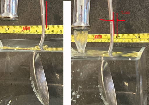 Figure 7.
The low pressure occurs at the upper half of the spoon as the water flows faster over the longer path. There may also be some Coanda effect at the bottom half as the water is deflected to the right. (This is a result of Newtons Third Law where a reaction occurs for every action).
This low pressure is what keeps aircraft aloft, allows sail boats to sail upwind, and lets ice yachts travel at high speeds (up to at least 5 times the wind velocity!).
Vector Geometry
The key to explaining Blackbird’s behavior lies in properly using vector geometry.
Vectors are simply arrows whose length and direction conveys both the magnitude and direction of an item.
For example a wheelbarrow’s handles can be raised, by a red vector force, preparatory to moving it. Leaning forward will tilt this vector. It can then be resolved into two forces: one (blue) lifting the handles vertically, the other (green) propelling the barrow horizontally forward:

Figure 8
The earlier diagram in Figure 5 of a wind flow speed and direction vector against an airfoil showed its lift and drag components.
Similar vector diagrams are used to add the various speeds and directions of wind, cart and propeller motions to give a resulting “Apparent Wind” on the propeller. This is the ‘Apparent wind’ (speed and direction) a prop ‘feels’. It is used to compute the force vector (magnitude and direction) on the prop. This vector can then be resolved into the two directions needed to explain the craft’s operation.
Velocity Vectors are easy to draw because they often represent something moving relative to the observer. An arrow from Left to Right can depict a West wind. The length of the arrow is proportional to its speed. But Force Vectors can be a little more complicated. For example, the force of someone standing on the ground can be depicted by a vertical arrow, point down. But that also implies a Velocity Vector function with the person’s feet sinking downwards into the earth! A fuller description includes a Newtonian Reaction Vector pushing back upwards at the same time. So a complete diagram would have an arrow pointing straight downward plus an equal and opposite upward arrow with their points meeting at ground level.
Note there is often confusion about named vector directions because of different usage conventions: For example a ‘West’ wind is said to flow from the West towards the East. At my house today the ‘West wind’ is blowing air from Perrysburg Eastward to Toledo. But at the same time a so-called ‘East current’ is seen in the Maumee river which is also flowing in the same direction Eastward to Toledo.
By convention a vector is drawn with the beginning of the arrow at the source of the wind or force, and with the head of the arrow pointing towards the destination where a result can be seen or felt.
For vectors it helps to consider the direction an item under consideration would appear to move, relative to some other object of interest. Think as though you were physically located on that object of interest and have the vector arrow point in the direction the item appears to you to be moving.
For example: If I am stationary on the ground in a 10 mph West wind I can show that wind graphically by vector V1.
 Figure 9
It is describing the speed and direction of the Air, apparently towards the East, relative to the me on the Ground, .
On a calm day If I ride my bicycle towards the East at 20 mph I will feel an apparent wind of 20 mph from the East in my face, as shown by vector V2 Air and Ground relative to Bike. (The air, and the ground, are moving Westward relative to me on my Bike). 
Figure 10
Now if the West wind is blowing at 10 mph and I ride my bike Eastward as before at 20 mph, I can add the two vectors (Air to Ground) + (Ground to Bike) by connecting them nose to tail. Draw a new vector from the first tail to the last nose (V3) to show the addition. I will ‘feel’ an Apparent Wind V3, red of Air relative to Bike (from the East) against my face, of 10 mph. 
Figure 11
Adding an extra dimension: imagine a calm day and I sit on my stationary bike, facing East, and hold a small flag in my hand. I move it from Right to Left, towards the North, at 10 mph then the flag will ‘feel’ a 10 mph North wind, as shown by vector (V4) below for Air relative to my Bike
 Figure 12
Now put those 3 situations together i.e. In a 10 mph West wind I ride my bike at 20 mph to the East and wave a flag from right to left at 10 mph (relative to bike)? What direction will the flag fly in? The answer is simply the addition of the relevant vectors, putting the tail of one at the head of the other.
 Figure 13
Add vectors V1 + V2 + V4 or Air rel. to Ground + Ground rel. to Bike + Bike rel. to Flag to get the resulting vector VA or Air relative to Flag connecting the tail of the first vector to the head of the last one. This new vector (VA) is the Apparent Wind vector for the flag. It shows the strength and direction of the wind felt by the flag i.e. about 14 mph from the NE.
Sailing Downwind Faster than the Wind
Using known values from existing high performance craft let us look at the details of an ice yacht, land-cart, or foiling catamaran, blue triangle in the diagram below, speeding along on a NE broad reach at about 25 mph, or two and a half times faster than the wind, in a 10 mph West wind, white arrow.

Figure 14
The velocity vectors above show that even though the sail only ‘feels’ an apparent wind of about 19 mph from the NNE, the ice yacht is traveling at a speed of 25 mph.
The wind force vectors on the sail are shown below. The red arrow (vector) is the resulting force from the apparent wind acting on the sail. It can be resolved into a lateral force (blue) to the SE resisted by sharp skates on the ice, wheels on the sand, or a keel in the water, plus a forward driving force (green) which propels the craft to the NE.
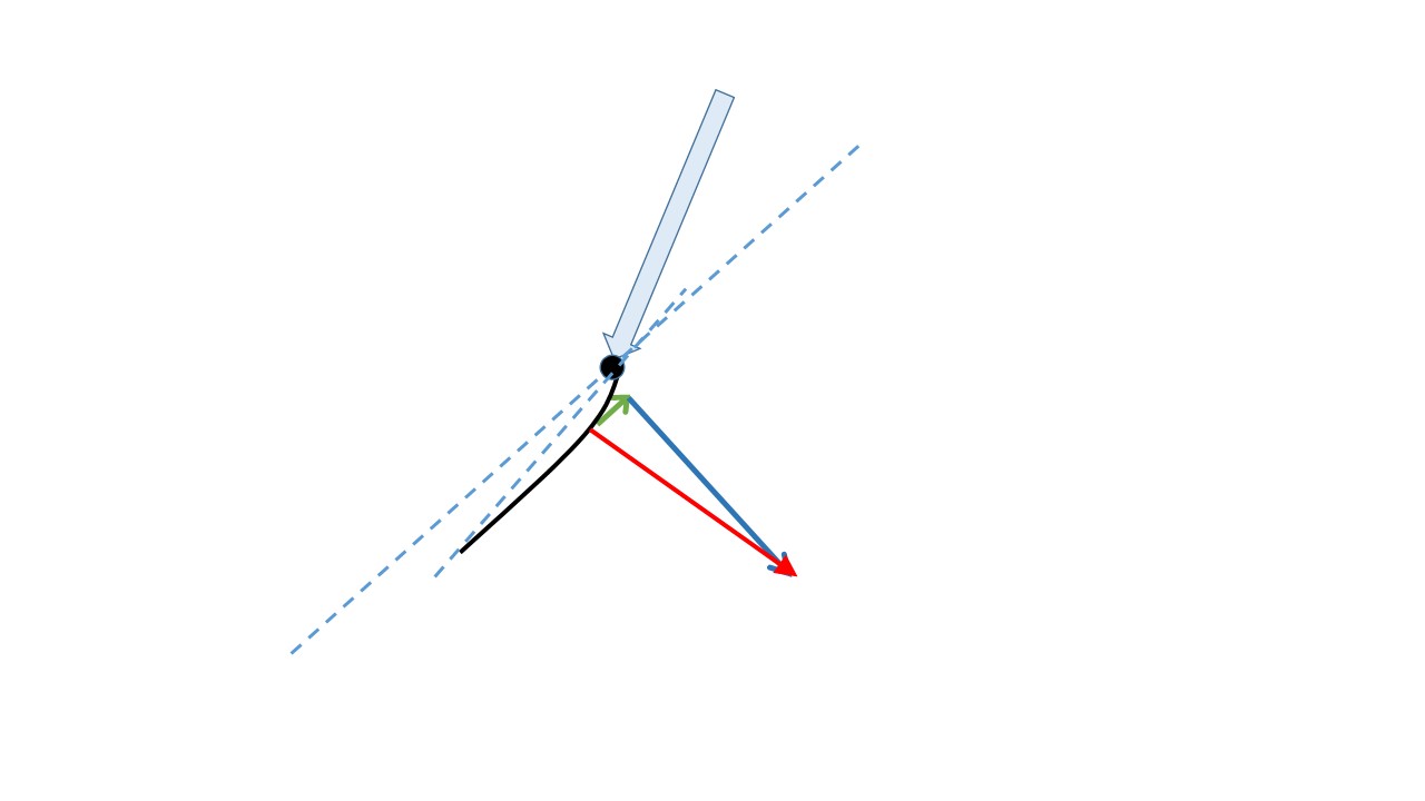
Figure 15
The velocity vectors below show that when the craft is travelling to the NE at 25 mph, it is making progress due Easterly, straight downwind, at about 18 mph, or about 8 mph faster than the 10 mph West wind, (and at the same time it is making similar progress Northward at 18 mph).

Figure 16
But, of course, if the sail craft bears away and tries to sail straight downwind it would feel a direct head wind, the sail would stall and the Bernoulli effect would no longer apply. With a stalled sail the craft becomes like our earlier balloon only travelling due Eastward at close to 10 mph at most and never finding the power needed to go faster.
A Thought Experiment
To address the main question of how to sail straight downwind faster than the wind let us imagine a (triangular shape) land cart, heading due East on the flat desert floor, with a steady 10 mph West wind blowing. On this cart we have a hypothetical horizontal supporting beam, blue line, with a track mechanism holding an ice yacht sail (same as the one used above) vertically on a sliding track which allows the mast and sail to be moved laterally in a North-South direction relative to the cart axis. If the sail is moved to the left, on the cart, at a speed equal to the forward speed of the cart then the sail ‘feels’, for a few moments, the exact same wind, force and direction, red, as the ice yacht sail felt, with its fixed sail, when it was travelling to the NE, in the previous case. The same red wind force on the sail is now resolved into East and South components representing the forward drive (green) and the lateral force (blue) resisted by the wheels.

Figure 17
An observer looking down from a balloon above would see, for a few moments at least, the sail moving in exactly the same direction as the ice yacht’s sail, and therefore generating the same lift and drag vector forces.

Figure 18
The picture above shows the initial position of the cart (in blue, left) with the sail amidships. The later position (green), shows the cart a few moments later, moving to the right (Eastward) and with the sail moving left (Northward) on its track, while the sail traverses a NE path over the ground.
The net driving force on the land yacht will be somewhat less than that of the ice yacht because of the energy needed to move the sail on the imaginary track.
Rather than having the complex imaginary supporting track for the mast why not let the sail simply be the single blade of a propeller? As this propeller revolves around its horizontal fore and aft axis the airflow will be very similar to the sails in the two cases above. By considering a short period of time we can ignore the small change in tilt angle of the sail as it rotates in its new propeller-like configuration. As the propeller blade rotates through its upper quadrant our overhead viewer would once again see air flowing over an airfoil similar to both the ice yacht and sand cart examples above. Add a second blade to the prop so while the upper blade is behaving as shown above when in the top quadrant of its rotation, the other blade is in the lower quadrant and supplies a similar Eastward direction driving force, but with an opposite direction (Northward) lateral force.
As the professor so often says, “I leave it to the student to resolve the details for the prop blades when they are travelling through the side quadrants (3 o’clock and 9 ‘-clock)”. The answer is simple: when the prop blade (sail shape) is travelling up or down, through the side quadrants, the resultant horizontal forces will similarly drive the craft forward, while the lateral vertical drag component, upward or downward, subtracts from or adds to the craft’s weight on the ground.
So now we can have a real cart going straight downwind (due East) at 18 mph with a propeller whose sail-shape blades move across the wind in a very similar manner to that of the fixed sail of the ice yacht travelling at 25 mph in a NE direction, in the same 10 mph West wind. Even though at 18 mph Eastward cart speed the apparent wind at the land cart body is 8 mph against it from the East, the propeller blades are still ‘feeling’ an appreciable, and useful, apparent NNE wind.
The propeller is turned towards the apparent wind by the belt drive connecting the prop shaft and the wheel axle. The drive force from the propeller hub provides a forward push to the top of its supporting mast, in the same manner that an airplane’s propeller ‘propels’ an airplane forward. The forward movement of the cart over the ground drives the wheels which turn the axle and puts tension in the belt to turn the prop.
An ice yacht, having the least drag resistance (from its skates) to forward motion of the three craft types considered, should have the greatest velocity of the three craft types considered here. A foiling catamaran, with a similar sail, should be the next fastest given that the drag of the foils through the water would be greater than that of sharp skates on ice. Our land-cart has low rolling resistance but it does have to supply energy from the rotating wheels to turn the prop against the apparent wind and so could be expected to have the slowest vehicle velocity of the three.
The magic of the Blackbird rotating propeller is that the blades can ‘feel’ an apparent NNE wind of about 19 mph even though the craft is running straight downwind, Eastward, at 18 mph in our 10 mph West wind, and experiencing an 8 mph apparent headwind!
But can the Blackbird propeller generate enough forward drive power after overcoming the drag of the drive belt on the wheel axle which has to rotate the propeller against the apparent wind? Work done is the force multiplied by the distance moved. For the ice yacht the lateral force is simply resisted by the skates on the, with no ‘distance’ moved laterally on the ice and so no work is done. But in Blackbird work is done equal to the distance the prop is moved against the drag of the wind. The solution lies in the force vector diagram, Figure 10 above, which shows the W-E and N-S vectors of the force on the prop.
Can Blackbird function in Zero Apparent Wind?
The thought experiment above reasonably demonstrates how Blackbird could perhaps travel straight downwind faster than the wind, but to get to that velocity, if it is travelling in a straight line, and starting from a standstill, it must first accelerate from zero speed to the velocity of the wind, and then exceed it. If the wind is 10 mph from the West then when the Blackbird has reached a speed of 10 mph to the East there will be zero apparent wind velocity as measured on the cart. How could the propeller mechanism create a drive force in zero apparent wind? A closer examination is needed of the cart and its operation while it accelerates straight downwind, starting at zero velocity.
Apparent Wind Direction on Blackbird and its propeller
To show the effect of wind on a sail, or on a propeller we first calculate the direction and strength of the Apparent Wind. Linking the 3 vectors, nose to tail, for Wind, cart and propeller motions of our land yacht needs similar attention to ensure each vector is pointing in the correct direction.
The cart (C) is moving Eastward relative to the ground at 5 mph, in a 10 mph West wind. More importantly for our vector addition, the ground is moving Westward relative to the cart at 5 mph! It is easy to visualize this by sitting on the moving cart and looking down at the ground.3. The prop is connected to the wheels by the belt and is rotating CW (viewed from aft). At the moment in time of this analysis the center of the prop blade, as it rotates over the top center, is travelling at 5 mph Southward relative to the cart. Adding the vectors of: Wind relative to Ground + Ground relative to Cart + Cart relative to Prop, gives the resultant Propeller Apparent Wind velocity and direction of 7 mph SW Wind relative to the Propeller.

Figure 19
Applying this apparent wind to the prop blade results in a force vector (F) which can be resolved into two components (Fw-e) and F(n-s). These two vectors show how the cart, not surprisingly, can operate successfully when travelling Eastward at 5 mph in a 10 mph West wind:
Cart Drive Details.
This paper uses a cart model similar to the record-making Blackbird and makes the following assumptions for ease of calculation:
- The wheels rotate at twice the speed (rpm) of the propeller.
- The wheels have a radius of 2 units.
- The drive pulley on the wheel axle has a radius of 1 unit.
- The drive pulley on the prop shaft has a radius of 2 units so the wheels rotate at twice the rate of the propeller, as on Blackbird.
- The propeller blade radius is 8 units or from the center of prop area to the prop shaft is 4 units.
 Figure 20
Using the above assumptions we get the convenient result that when we resolve the wind force component on the prop into West to East drive (Fw-e), and N-S prop turning (Fn-s) we find that the effect of a F(w-e) drive force equal to a positive F(n-s) force on the prop will provide equal forward drive power. If the Prop force Fn-s is negative or Northward, and equal in magnitude to the Eastward Fw-e drive then the two will exactly cancel and there will be no net drive force to the cart or its wheels.
Step by Step Detail from Zero to Twice Wind Speed Straight Downwind in a Prop Driven Land Cart
To address the question of FTTWDDW (Faster than the wind dead down-wind) we now use the vector analysis method to illustrate the operation of accelerating , step by step, from standstill to some equilibrium speed, hopefully greater than the wind speed.
The cart’s propeller blade is continuously pitch-adjusted, by the sailor, to an angle of attack of about 15 degrees to the apparent wind to optimize the Bernoulli lift effect.
At Zero cart speed, and 10 mph West wind the cart is facing East with the brakes on so the wheels do not turn. The propeller is pitched straight into the wind, or ‘feathered’, roughly pointing West to East resulting in a small Fw-e. At this stage there is also some general drag from the West wind trying to push the cart assembly to the East.
 Figure 21
Releasing the brake will allow the cart to start rolling Eastward, with some CW prop rotation (viewed from astern) as it is turned by the belt.
Adjusting the prop pitch angle will result in a wind force on the blade. Looking down on the blade from above you can see that rotating the blade’s CCW will result in a wind force pushing on the concave side of the blade trying to turn the propeller shaft CW (when viewed from astern). The prop blade is pitch adjusted for a 15 deg angle of attack to the West wind resulting in a NNWW wind force on the blade (when viewed from above). At 10 mph West wind and Cart speed 1 mph to the East Figure 15 shows a small green Fw-e pushing the cart Eastward, and a significant blue force Fn-s driving the prop CW and consequently rotating the wheels to drive the cart Eastward.
 Figure 22
(If the pitch were adjusted in the other direction (CW) to make the wind push against the convex top side of the airfoil then the blade would rotate CCW and drive the cart upwind.)
At 5 mph Cart speed the cart is easily driven by the green Fw-e and the blue Fn-s vector components
Figure 23
At 10 mph West wind and a Cart speed of about 9 mph Eastward the vectors resolve into a single component Fw-e pushing the prop Eastward through its hub bearings. This force on the cart structure is resisted by an equal and opposite force from the ground at the drive wheels which rotates the axle and turns the propeller CW via the belt.
 Figure 24
As the cart speed reaches 10 mph the North-South Force vector flips direction and begins to add a drag force to the propeller retarding the acceleration.
 Figure 25
At 15 mph cart speed it is still accelerating driven by the green Fw-e vector, even though it is being increasingly resisted by the smaller, but growing, blue Fn-s vector in a Northward direction
 Figure 26
At 10 mph West wind and 20 mph Cart speed to the East the apparent wind on the cart body would come from the East and a flag on the cart body would fly straight back. The apparent wind on the moving propeller now comes at about 22 mph from the SSE. The force on the prop resolves into roughly equal forces: Fw-e Eastward driving the cart forward, and Fn-s Northward resisting the rotation of the prop. As described above these two forces cancel each other out in the belt tensions resulting in no net forward drive force on the cart. This cart arrives at an equilibrium speed of about 20 mph dead downwind to the East (twice the wind speed) with no further acceleration. Fine tuning the prop blade area and pitch angle, drive train gear ratio, etc., could provide further acceleration. It is noted that the full size Blackbird is recorded at travelling DDW at three times the wind velocity,

Figure 27
Added to the opposing force Fn-s is the drag of the whole craft running into an apparent 10 mph East wind. So somewhere in this speed range the acceleration will cease and the craft will continue to run at a steady speed. But it is now travelling straight downwind at about twice wind velocity.
So does the cart wheel drive the prop, or vice versa? I think it is a bit of both! I’d say one component of the wind force on the prop, Fe-w, pushes the cart forward which turns the wheels which pull the belt which drives the prop. At the same time the other component Fn-s is either assisting at speeds below wind velocity or retarding the cart at higher speeds.
Other Thoughts
If you are comfortable with the idea of how the device works then perhaps you should be able to appreciate what would happen in the following conditions:
- The prop has a clutch on its hub, and a brake. Disconnect (open) the clutch, apply the brake to the prop, and then tow the craft from standstill to 10 mph Eastward in a 10 mph West wind. Release the prop brake and the prop will just sit there – no rotation – because there is no apparent wind on the cart at 10 mph.
- At standstill open the clutch and release the brake. In a 10 mph West wind the prop will spin. Tow the cart to the East at 10 mph. The prop will eventually stop spinning, from friction, because there is no apparent wind. Similar to situation 1 above. Now release the tow. As the cart slows the prop will start to rotate again. With the clutch open the cart will finally stop with the prop spinning fast.
- In a 10 mph wind, tow the cart to 10 mph with the prop stationary, clutch open and prop brake on. At 10 mph release the prop brake, release the tow and engage the clutch. The prop will start spinning. The cart will slow to say 9 mph because of the inertia of the prop and the energy needed to spin it up as supplied by the kinetic energy of the moving cart. Now the prop is extracting energy from the wind speed to ground velocity difference. As shown in fig. 18 above the system can extract useful energy and accelerate the cart to a velocity greater than wind speed!
- Could there be a way to exploit the power generated by the wheel driven propeller in zero wind seeing that this was almost done when the apparent wind on the cart was zero in example 3 above? Towing the cart Eastward at any speed, in a zero wind velocity, and then releasing it, at first sounds similar to the above situation of 10 mph cart velocity Eastward in a 10 mph wind from the West.
 Figure 28
But plotting the vectors quickly shows the apparent wind on the prop now comes from the SE. With a 15° angle of attack the forward drive vector to the East, green arrow, is smaller than the North-South force to the North, blue arrow, and so when they pull the drive belt in opposing directions, the net drive will be negative and the craft will quickly come to a halt.
It would be interesting to see what speeds Blackbird could attain if it started to turn towards the wind. I have since read that Cavallero did alter Blackbird a little – he widened the axle for stability against the torque of the propeller- and reportedly travelled straight upwind at twice the wind speed.
Other Unlikely Propulsion Methods:
1. Straight downwind sailing, faster than a very low wind velocity, can be done on flat water, by experienced racing windsurfers who vigorously ‘pump’ the sail back and forth. But this is adding energy (human) from an exterior source and cannot be accepted in our case.
2. I remember clearly, about 45 years ago, looking with my young son at our first skateboard on the smooth varnished floor of the Algonquin Island clubhouse and wondering if there was any way it could be propelled without putting one’s foot to the ground. I erroneously concluded that was impossible, but not long later others showed us how to do it with a “tic-tac” motion, pumping the board forward by twisting it back and forth, while simultaneously popping the front wheels forth and back.
3. Perhaps the hardest is to levitate oneself by standing in a bucket and pulling up on the handle (which principle may come to mind when you first hear of the Blackbird story). But even that improbably could work, at least momentarily, by performing an energetic series of hops. Or have I just invented a ‘Pogo Bucket’?
4. In my year (1965) of wandering through India I did watch out for the infamous rope trick and actually met these great characters who appeared as though they might be keepers of the secret:

 Sadly I never did see the rope trick performed.
5. I close with my disappointment in the late but brilliant magician Doug Henning who long ago told us from the stage of Ryerson Theater in Toronto, on his return from visiting the Maharishi Mahesh Yogi in Switzerland, that he would soon be genuinely levitating. He failed to truly do that. Photos similar to the one below were created of the Yogi’s followers bouncing on trampoline-like devices. Doug tragically died too young of a liver problem which he falsely believed (according to Wikipedia) could be cured by his faith in the Maharishi’s “Transcendental Meditation” methods.

Sea-Bee (OH-10)
V20 2023/10/02